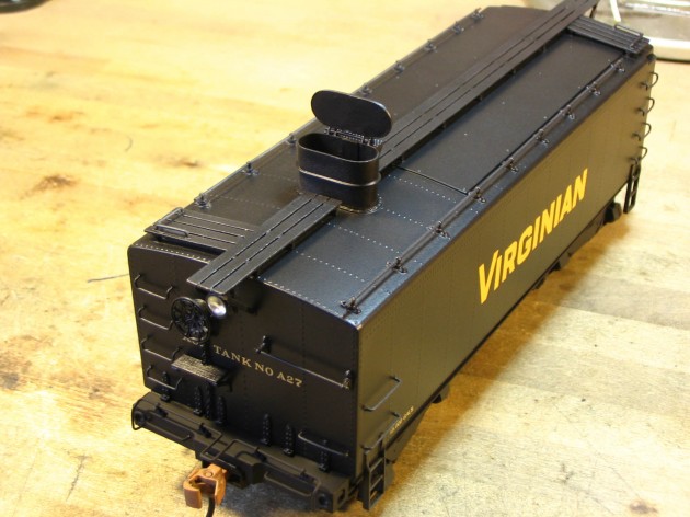
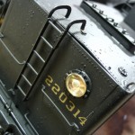
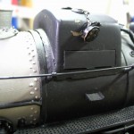
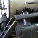
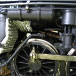
Steam Tender Conversion and Ultra-Detailing in “O” Scale…Virginian Coal Tender #803 to VGN Aux Tank #A27

The Prototype…


VGN Aux Tank built from one of the 14,400 gallon AB/AD tenders…

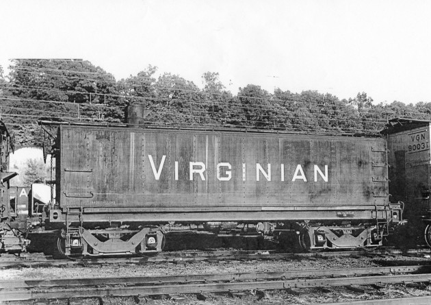
Although few in number, the Virginian Railway was well know for their massive articulated steam locomotives, particularly their AB/AD Class 2-8-8-2’s and AE Class 2-10-10-2’s.  In the late 1940’s and early ’50’s, with even more new electric locos making inroads, the VGN scrapped some of those big steamers and salvaged the coal tenders from seven of them. The tenders that were saved were sent to the Virginian’s Princeton Shops, where they were converted to water-carrying Aux Tank cars.

Effectively, the coalboards were removed and sheetmetal covers were fabricated to seal off the top and the end of the bunker. The cistern ring and hatch was narrowed and extended, a freight car style AB brake system was installed, as well as freight car running boards, hand grabs, backup light and safety appliances. The front end beam was modified to accept a coupler instead of a drawbar.

The intent of the Company in building these was to couple them to the rear of existing steamers to double their onboard water supply, thereby reducing or eliminating a number of water stops. Other railroads in the east built aux tanks (aux water cars) too, most notably the N&W and Reading. These VGN cars were also used in MOW and other service.

Of the seven cars built, five were 14,400 gallon tanks taken from the AB/AD 2-8-8-2’s and two were 13,000 gallon tanks taken from the AE 2-10-10-2’s.  The first five were rebuilt into aux tanks after WWII and the last two were rebuilt in the early 1950’s.

The Model…as delivered


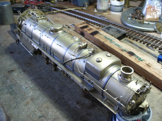
For this commission, the client shipped me a complete, pristine model of one of the AE tanks from the recent run of the Sunset/3rd Rail VGN 2-10-10-2’s. The client had planned this conversion prior to the Sunset models being completed, and ordered just a tender for this purpose.

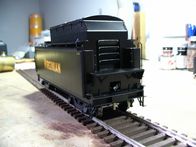
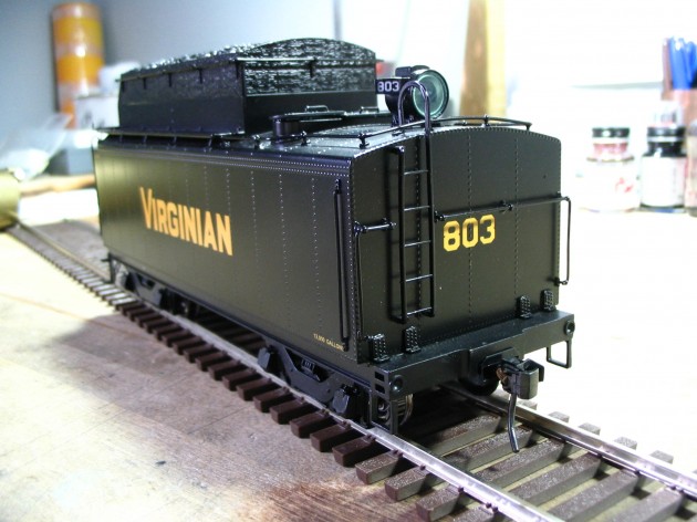
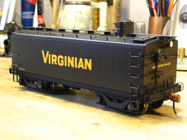
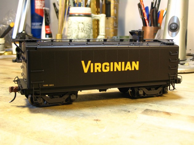
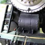
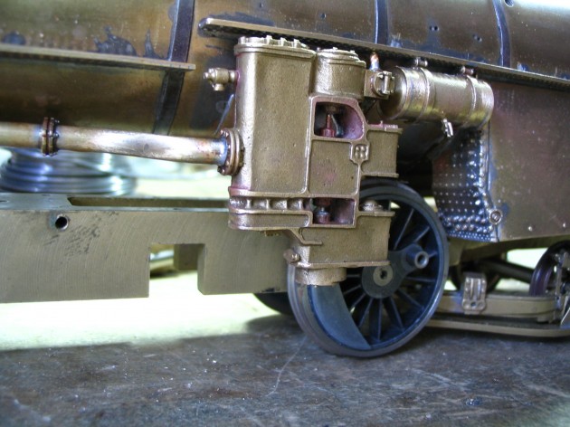
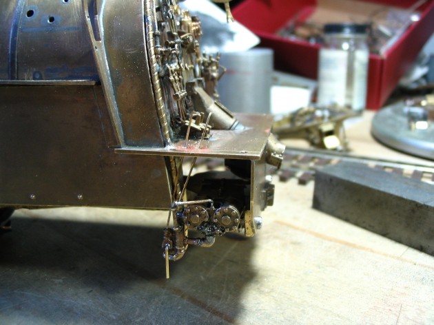
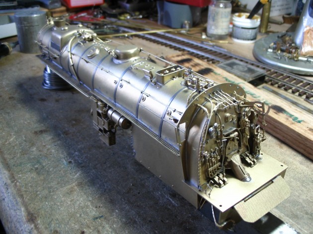
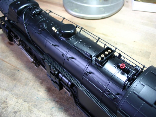
Here’s a few shots of the brand new tender as delivered to me…

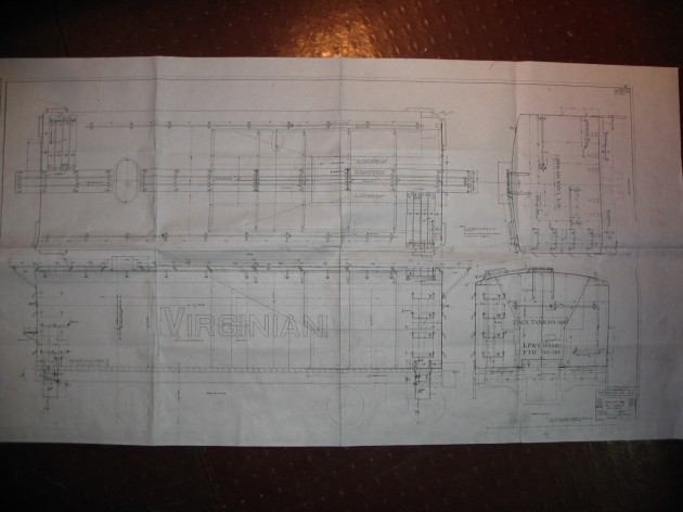
As was done at Princeton, the goal here was to convert the stock coal tender into the modified aux tank. Fortunately, the client was able to supply me with a copy of the actual 3/8″ = 1′ erecting drawing used by the VGN to make these modifications. Here is an image of that print.

The Conversion…


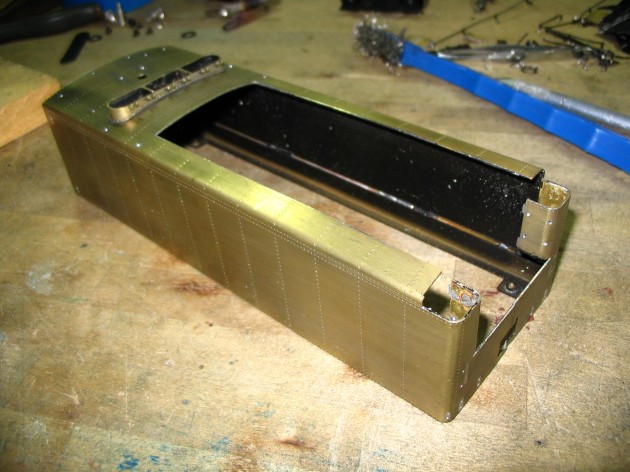
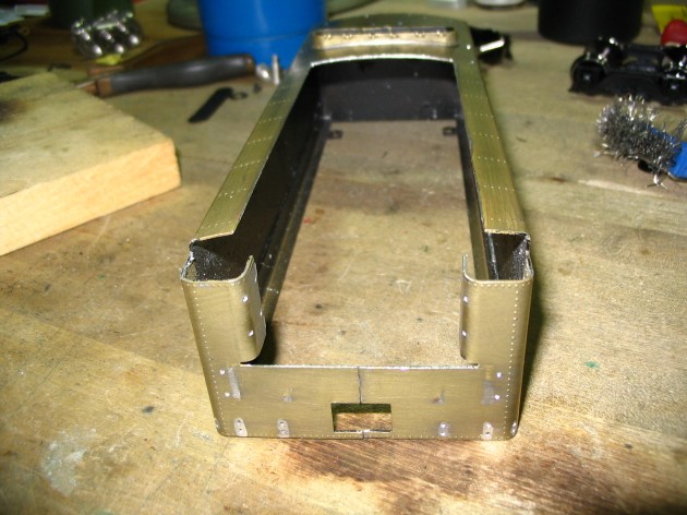
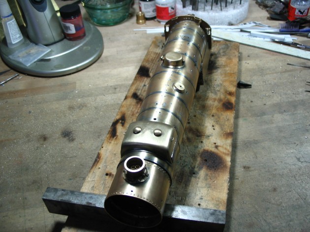
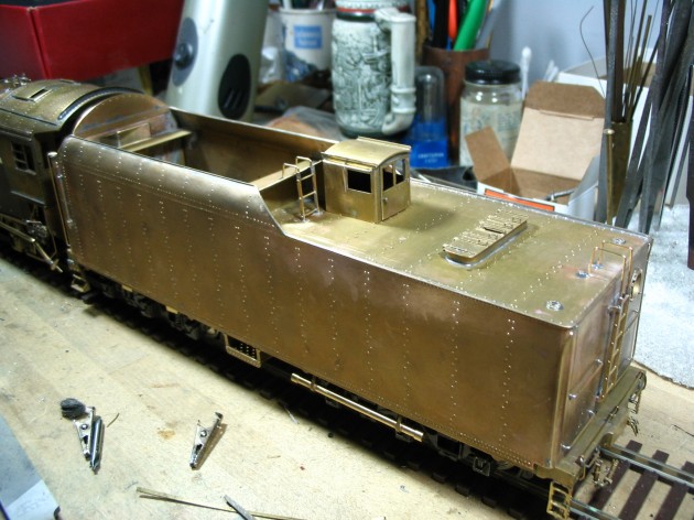
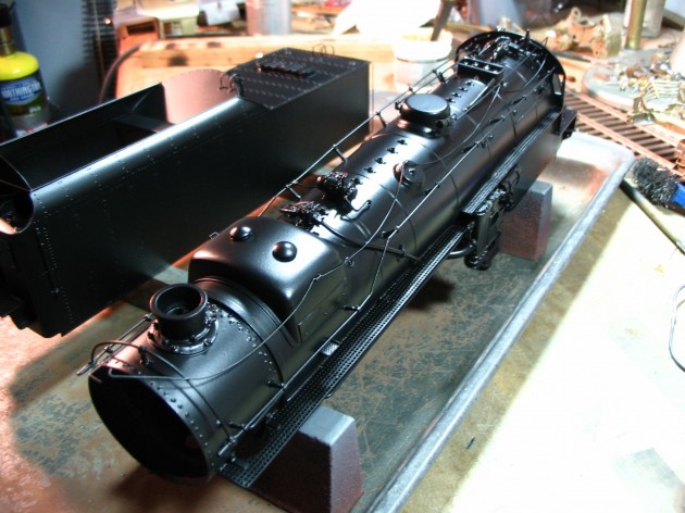
The rebuilding process to create an aux tank from this stock tender was EXTENSIVE. And even though the original paint and lettering was pretty good, it could not be saved and had to be stripped. Here’s a few shots of the model after all the details, un-needed parts and paint have been removed.

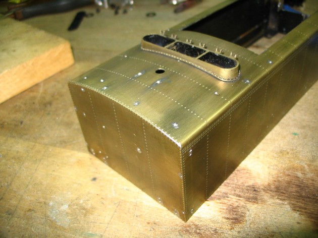
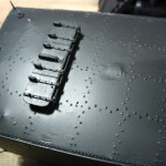
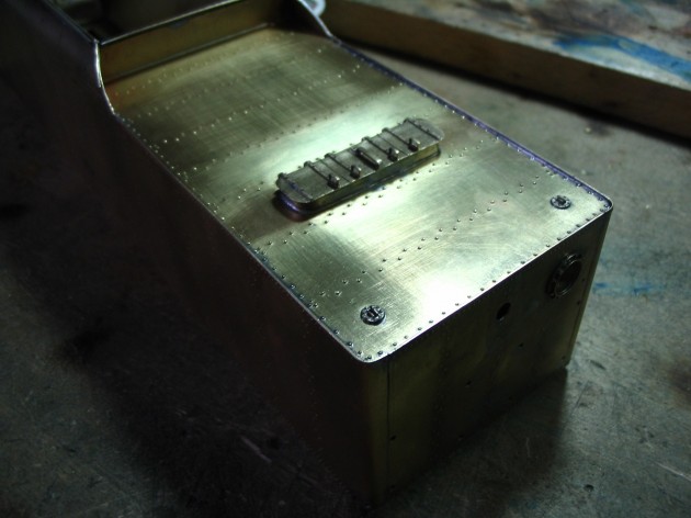
As with the prototype, new sheetmetal covers (with rivet detail) to cover the top and end of the coal bunker were fabricated and installed.

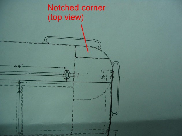
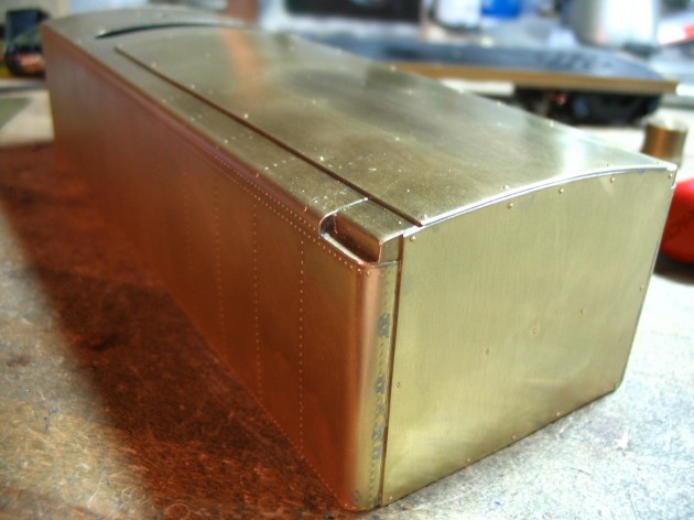
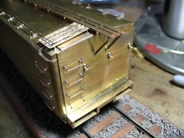
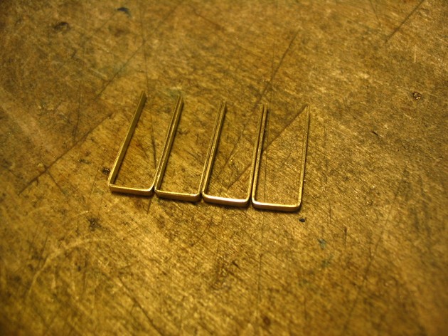
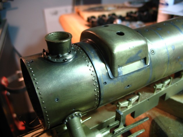
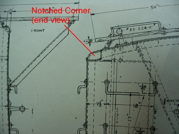
Accurate end fillets then had to be fabricated to fill in the openings between the new end and top sheets. There was some confusion about just how these were to be rendered, since no good closeup images of the corner treatments exists. Looking at the Company print, in two out of thee views (end and top) it would appear that there is a 18″ long x 4 1/2″ wide notched step at the joint. That made sense, as the Princeton Shop would have had limited metal forming capabilities, and creating a complex, compound curved section of steel sheet to perfectly fill in that space with no step or notch (just for the sake of asthetics) would have been way too much work.

Here are some closeups of the print that shows the notched fillet…
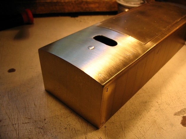
Here’s a close up of the completed engineer’s side fillet installed, maintaining the correct length, width and depth of the notch (as per the print).

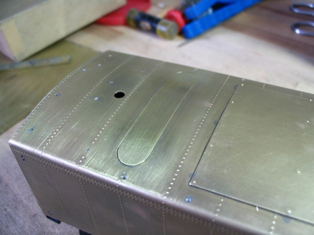
Princeton reduced the width of the cistern deck water hatch on these tanks, so following suit I filled in the old opening with several layers of brass, to accommodate a smaller filler.  

After soldering in the new filler sections, the top of the tender was filed smooth to blend all the seams together. The eched rivets were filed off too, but will be restored prior to painting.
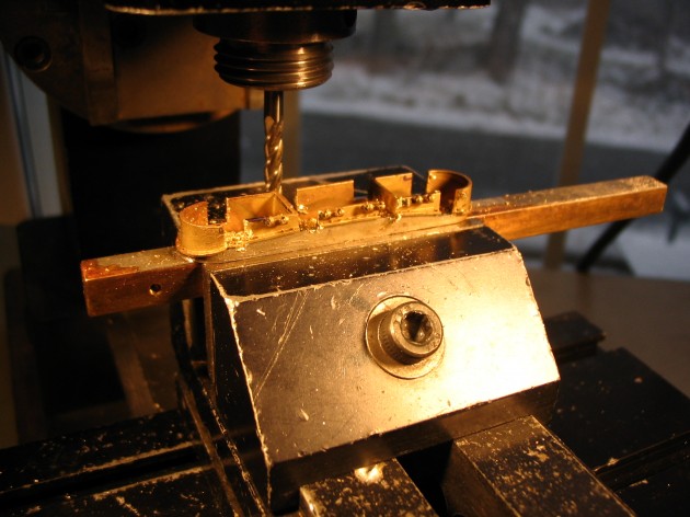
Once the old opening was filled and the new one cut in, it was time to turn my attention to modifying the water hatch ring and lid. The ring casting was fixtured into the milling machine, and two segments near the middle were removed.

The remaining center section and two small curved end sections were then fixtured, and joined together with solder. A new, extended center colum, lid and platform was fabricated and joined to the smaller base ring to complete the assembly.

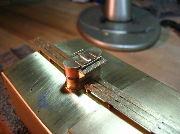
Here’s the completed hatch assy. installed in the new cistern deck opening (with the running boards mocked up).

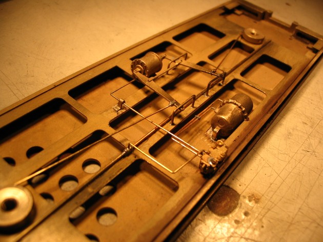
Using the prototype as a guide for component location, a full AB brake system was made up and installed…

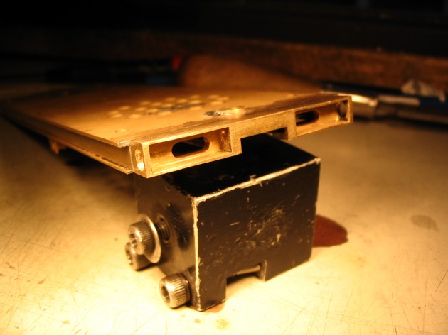
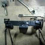
New front end beam was fabricated per the print and attached to the deck…

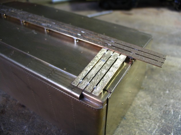
Running boards and end platforms were installed…

Next up…drop grabs, end grabs, deck railings, and roof walk end supports. All parts were custom fabricated…

Yard steps and rungs were individually fabricated from brass strip…

Ajax brake box, brake chain and brake step were added, along with coupler cut levers, back up light and tank stays, completing the fabrication, and making the model ready for paint/lettering.

The Completed Model…


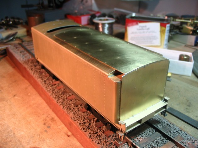
3/4 View “B” end…

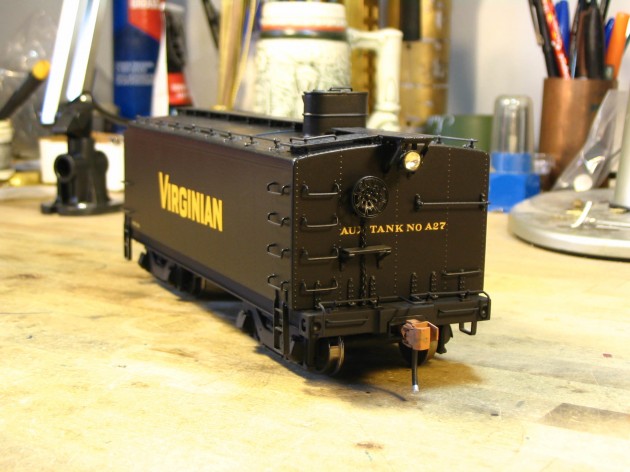
Side view…

Top View “B” end…

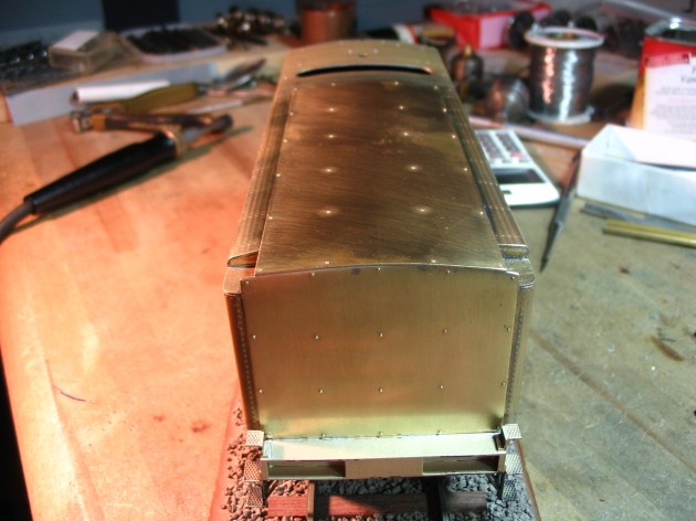
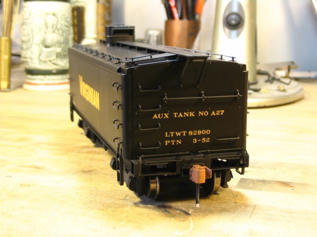
“B” end…

“A” end…

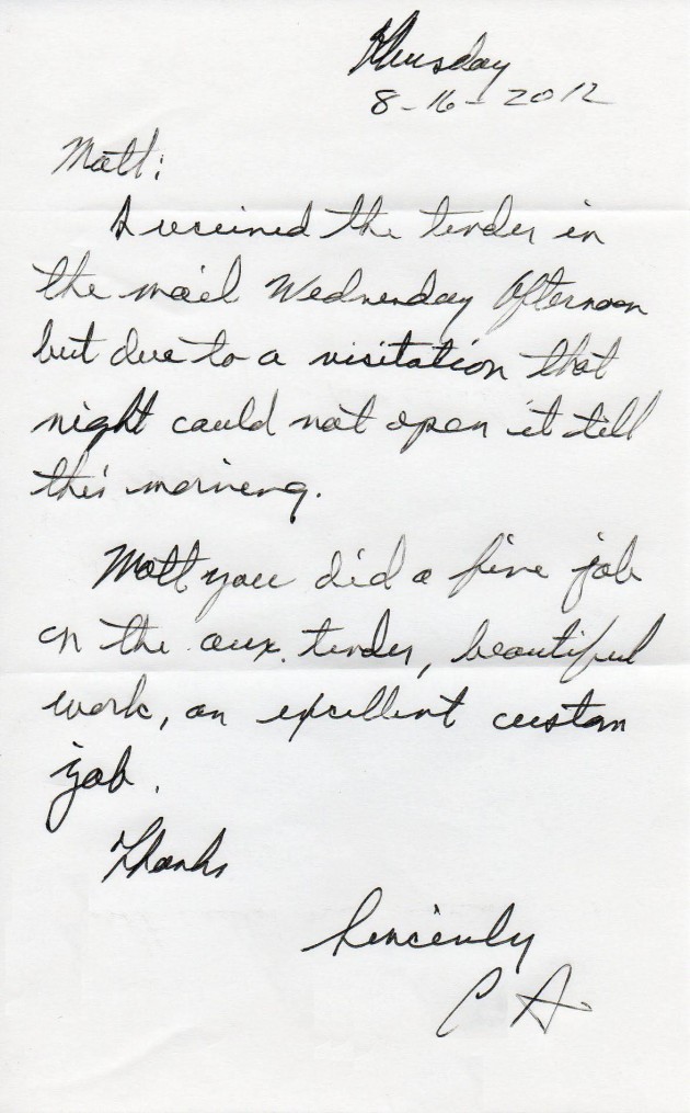
After I shipped the finished model to the client, I received this letter in the mail…
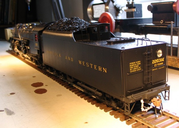
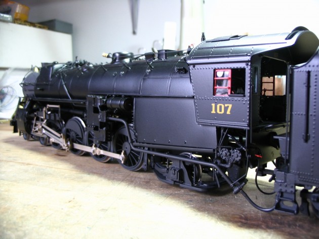
Steam Locomotive Ultra-Detailing in “O” Scale…N&W K1 #107

HERE WE GO AGAIN!!!

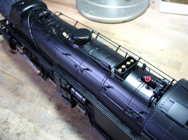
A commission was received from a well know publisher and modeler. Here’s a teaser…
The Client  had originally contracted with a self described “1/4″ custom builder” out of New Jersey to take an old Toby USRA Heavy Mountain,  and completely rebuild it into an accurate representation of a Norfolk and Western Class K1, 4-8-2.

The client paid good money for the original work, but the final product from the Jersey builder was, for lack of a better term…ABYSMAL. I could NEVER, in good conscience, turn out a product that poor (that had my name on it), and THEN stoop so low as to expect payment for something so inferior.

Here are a few images of the locomotive when I first received it from the client. This is also the way the Client received the loco from the original builder…YIKES!


(click on any of the thumbnails and click again after they open for a full sized view)

When I first agreed to take on this project loco, the Client had wanted me to strip it,  “tune it up”  by reworking  some of the most glaring issues, and then repaint it and install DCC w/sound. After a thorough going over, I let the Client know that the list of errors and issues literally ran well into the hundreds, and the only way (IMHO) to make this loco “right” was to completely “kit” it, back into its original, individual components and start over. That included torching apart the boiler.

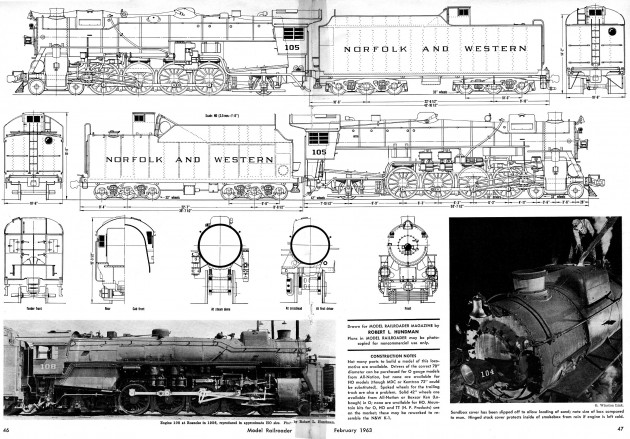
N&W K1 drawing, Model Railroader, February, 1963

(image courtesy Kalmbach Publishing  Co.)

The first step in the process was to strip the paint and blast the loco clean. The second was to take the torch and do a total disassembly, removing every last component.

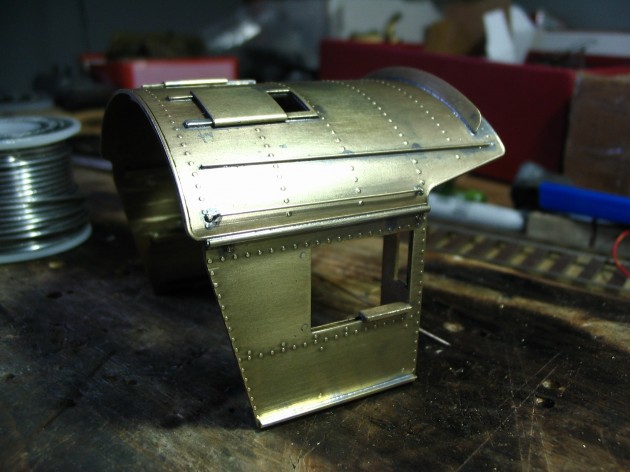
After it was taken apart, the boiler courses were all individually re-rolled (to the correct diameter) and reassembled, including the firebox, and a new backhead was created. The unique N&W domes, which were originally lost wax cast for the project the first time around, were not even close to anything that was on the Roanoke Shop’s prints (they were too large), so they were totally reworked and carefully massaged to match the actual N&W specs. The boiler, firebox, boiler bands, cab front bulkhead, and domes were then re-assembled into a straight, credible copy of an N&W K1 boiler.  Here’s a shot of it after assy.

Here’s a closeup of the sand dome being reworked….

Once the basic boiler was completed, I turned my attention to  the cab. The one supplied was a facsimile of an N&W sports cab, but it had several errors. Here’s the rebuilt, corrected cab, including accurate, custom made, half- round rain gutters and angled toe boards. NOW she’s N&W!

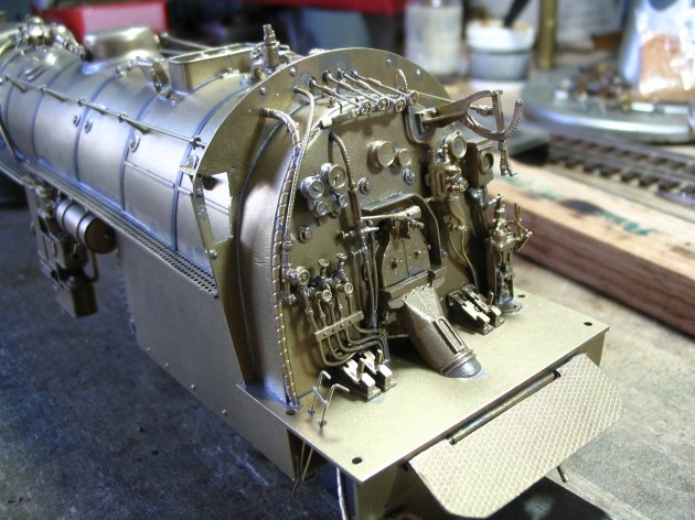
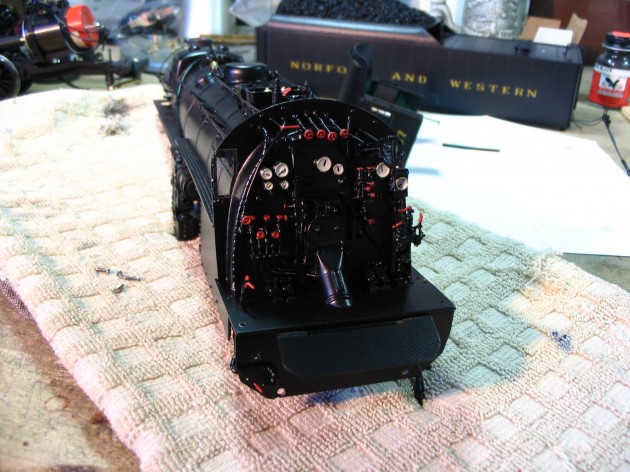
At this point I needed to rework the cylinders and fit the rebuilt boiler to the frame, and the cab to the boiler. Once complete, and happy with the fitment, I started detailing the backhead. Like everything else on this project the original builder detailed it sparsely, and incorrectly. Using info supplied by the N&W Historical Society, I did it up based on original images. Here’s the end result.

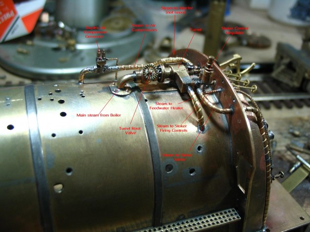
Many locos have a firebox-top-mounted turret, that serves as a steam distribution manifold for the loco accessories (injectors, stoker jets, stoker motor, feedwater heater, compressors, etc.). Many larger loco were also equipped with a sheet metal shroud or cover that encloses the turrent and its associated piping. The N&W K1, however, had an open turret, with all piping exposed. Here it  is accurately modeled. I have included lables that indicate the routing of each of the lagged steam lines.

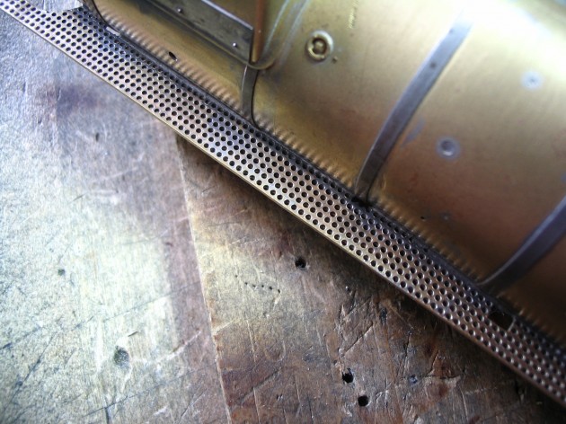
The N&W used a perforated running board material on their locos. The ones originally “attempted” by the first builder were warped (excessive heat) and poorly executed, so they were removed and thrown away. These were made and carefully fitted using similar material from Special Shapes.

http://www.specialshapes.com/index.html

Once the running boards were installed, all the appliances could be hung, including the power reverse, Westinghouse dual compressors, compressor suction filters, Worthington BL4b Feedwater Heater, and associated tanks and piping.

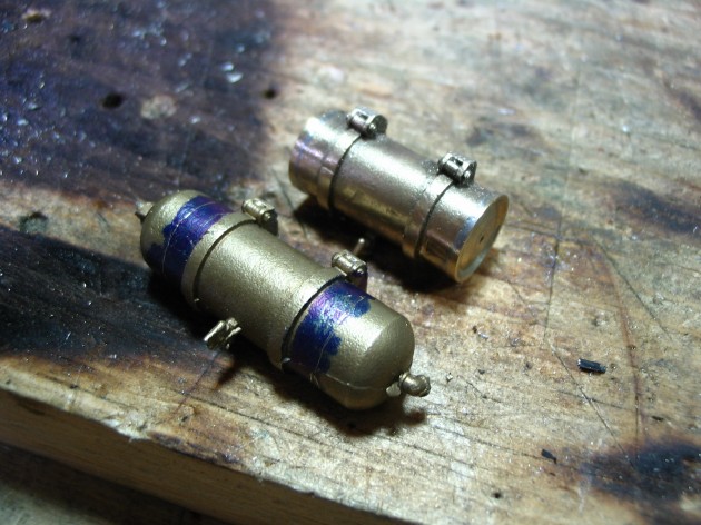
The air tanks originally supplied were not correct. They were too long and had plain, convex ends, rather than the appropriate inset, convex ends. I turned new ends for all tanks, cut off the existing ones (shortening them in the process), and applied the new ends. Here’s a shot of before and after.

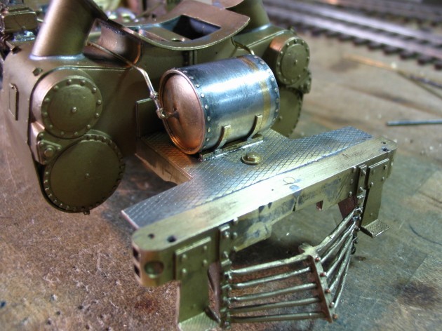
The large, pilot mounted air tank was a wreck, and was tossed. Here’s a new, scratchbuilt replacement with correct lower mounts and piping, along with a new pilot deck and reworked pilot.

Here’s the installed BL4b and piping…

Here’s the new stoker, supply piping and control rods.

The tender needed some attention as well. The original cistern deck was all dented with the seams broken lose from the sides.  The original builder has installed a large weight in the tender that came lose when it was shipped to the client. The weight, bouncing around while in transit, trashed the deck. I made and installed a new deck, and soldered shut all the opening doors, hatches, and what have you.

There’s NO BETTER WAY to trash a great paint job than with locomotive parts swinging open and closed.

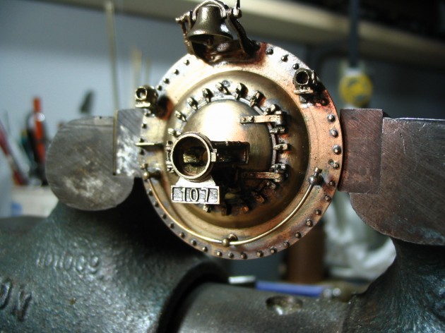
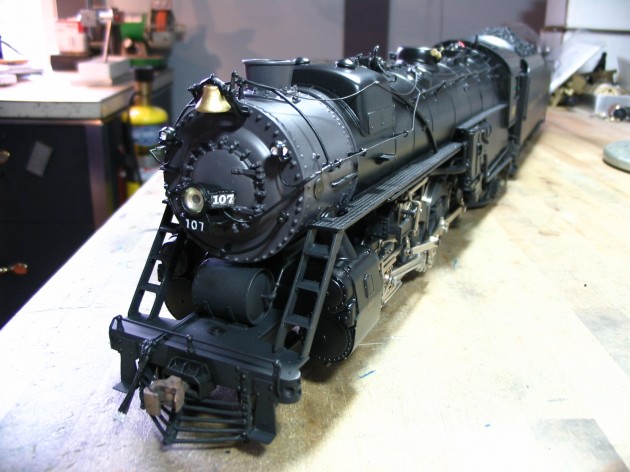
Completely rebuilt, scratchbuilt smokebox front, with individual NBW castings, and hand-cut numerals from 0.005 brass sheet.

Two views of the completely detailed boiler…

(Engineer’s side)

(Fireman’s Side)

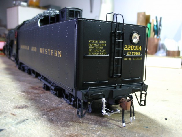
Finshed tender…

Many of the N&W K1 Class used second-hand tenders, purchased from the NKP. This one was originally from a US Hobbies NPK Berk.  The deck, coal boards, bulkheads, collars, ladders, grabs and other details have been extensively tweeked per the prototype, as well as the addition of a doghouse.

All superstructure sheetmetal is ready for paint. Here’s a shot of the parts, just out of the paint oven.

Once the boiler and tender were fully detailed and painted, it was time to turn my attention to the chassis.

WHAT A NIGHTMARE!!!

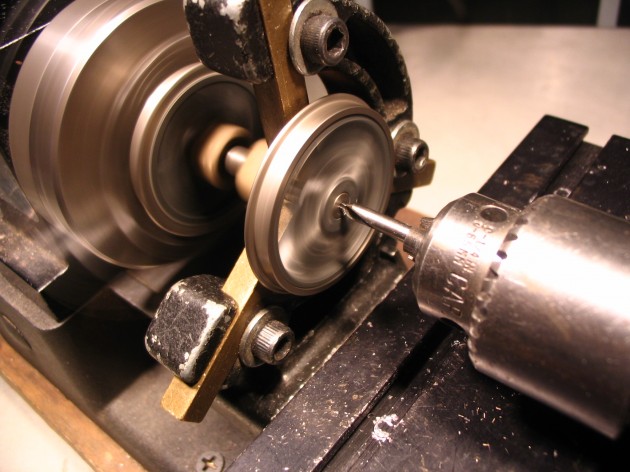
The last builder performed some soldering on the boiler with it installed on the chassis, with the drivers still in the frame. He dribbled flux on the driver tires (and didn’t clean it off), which left them corroded and deeply pitted. The ONLY way to remove the damage was to turn the tires. They were 0.172 wide from Toby, so I turned them to 0.145 (the current NMRA spec.), resurfaced the treads, and centerdrilled the axle ends, for a prototypical appearance.

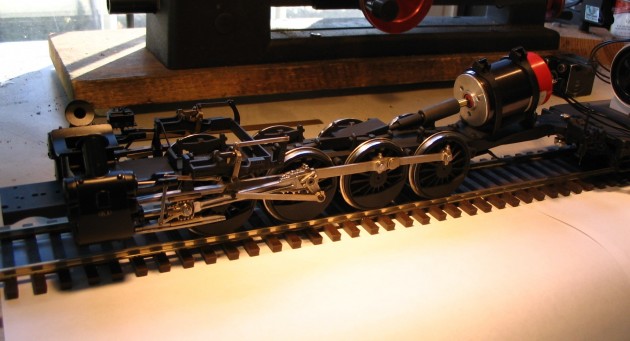
Like many older locos, the main rod, side rods and pins were worn and sloppy. All rods were bushed and new steel pins were made as replacements. The original crosshead guides were made of brass, and looked poor. A new, step-cut set was made out of 12L14 steel, that were then polished and installed. Once I had the assembled mechanism rolling soothly, I applied the reworked valve gear, upgraded all fasteners to micro hex-heads, installed the gearbox and a Maxon high efficiency can motor. Here’s an image of the completed, painted assy. being tested.

With all parts fully in paint, it’s time to apply decals, a clear overcoat,  and do a final assembly.

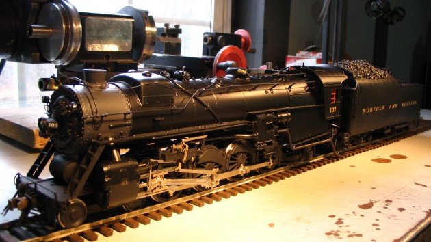
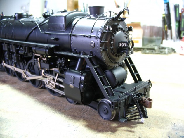
3/4 Fireman’s Side/Front

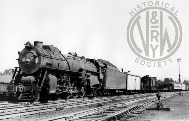
K1 #107 on a wreck train…

(image courtesy N&W Railway Historical Society)

Rear View, Fireman’s side…

Left, rear cab…

Left, rear tender…

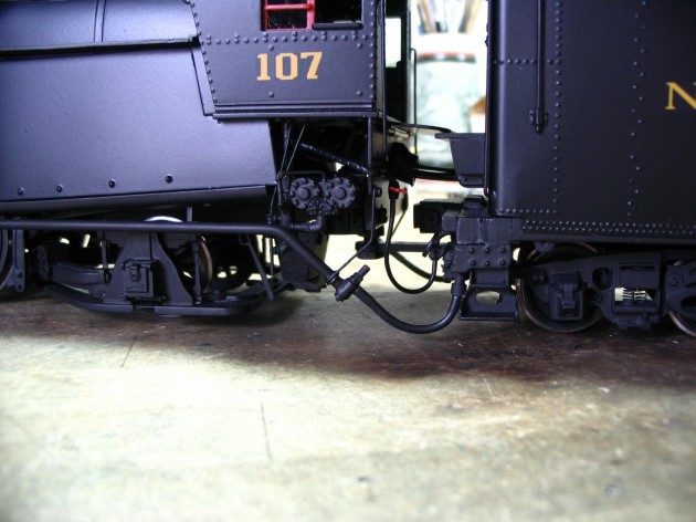
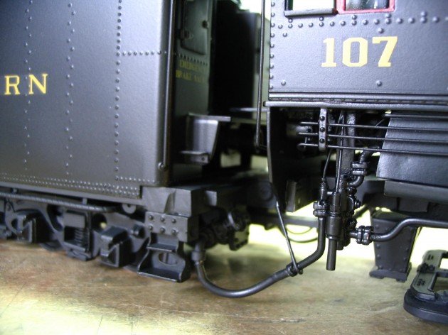
Engine-to-tender connections…Fireman

Engine-to-tender connections…Engineer


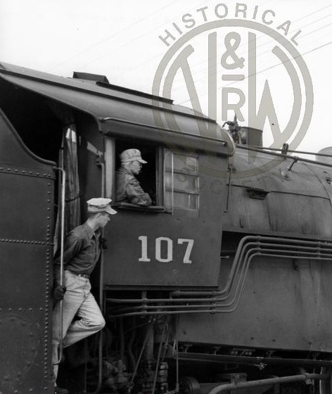
Cab of 107…

(image courtesy N&W Railway Historical Society)

Fireman front…

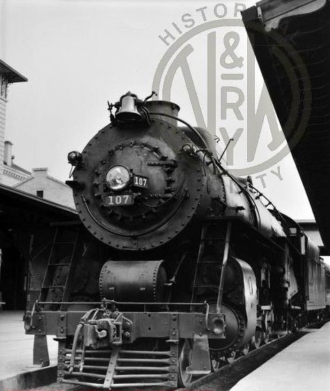
K1 #107 front end…

(image courtesy N&W Railway Historical Society)

Engineer front…

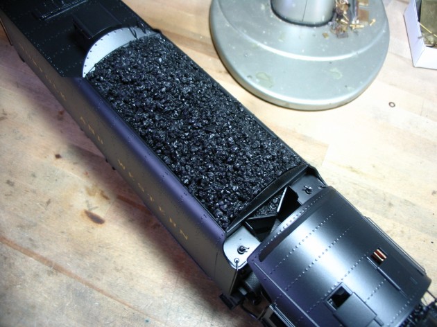
Cab roof and coal load…

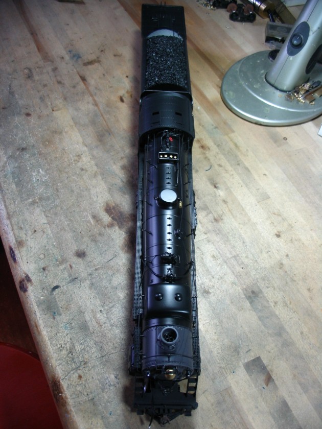
Overhead,  entire loco…

Fully detailed backhead…

Topside details…one more time

The Loco arrived the Client’s house, and he was very pleased with the results. Here’s an email he sent me, not long after unpacking it:

Re: Inspection Report…

Matt, I put the new K1 on the layout to get some photos and just generally look it over. It is spectacular!!! Everything worked fine and it runs very smoothly when it’s not on my dirty track ;-). I wish the MRC decoder I selected had a Rule 17 lighting feature. I don’t like it when the headlight goes out in reverse.

So, I am 110% pleased. It exceeds all of my expectations. I thank you! Have a Happy Thanksgiving. I will with my new toy.

Best regards

Joe

After he gave it a thorough inspection, he posed the loco for some photography. Here are shots he shared with me.

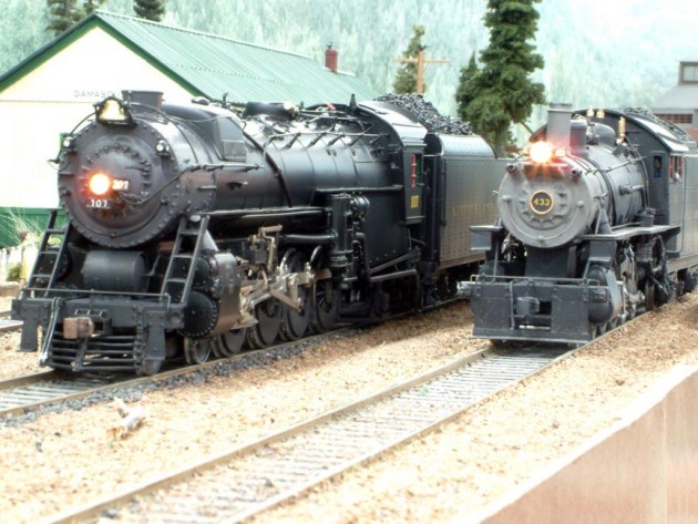
#107  makes her debut @ Damascus, VA.

K1_M_Damascus

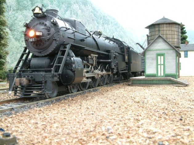
K1 takes water at the tank…

K1 at Damascus_VA


Evolution of the 40′ Steam Era House Cars of the Delaware & Hudson


USRA Single Sheathed, 40 foot “Government”  boxcar, built in 1919, series 17001-17500. This is #17225, as she appeared after her 1937 rebuilding, and wearing the new post 1950 D&H paint scheme. Note the Viking roof, that was a part of the upgrading process.  Cars got either a Murphy Raised Panel roof, Climax Radial, or a Viking Ribbed. Number assignments as to the type of roof applied to which car were random. Inside height was 9′-0″. (image courtesy Steam Era Freight Cars)

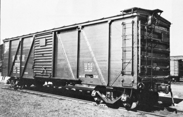
Green Island 17513, 3/4 builders (image courtesy R.P.I. D&H Collection)

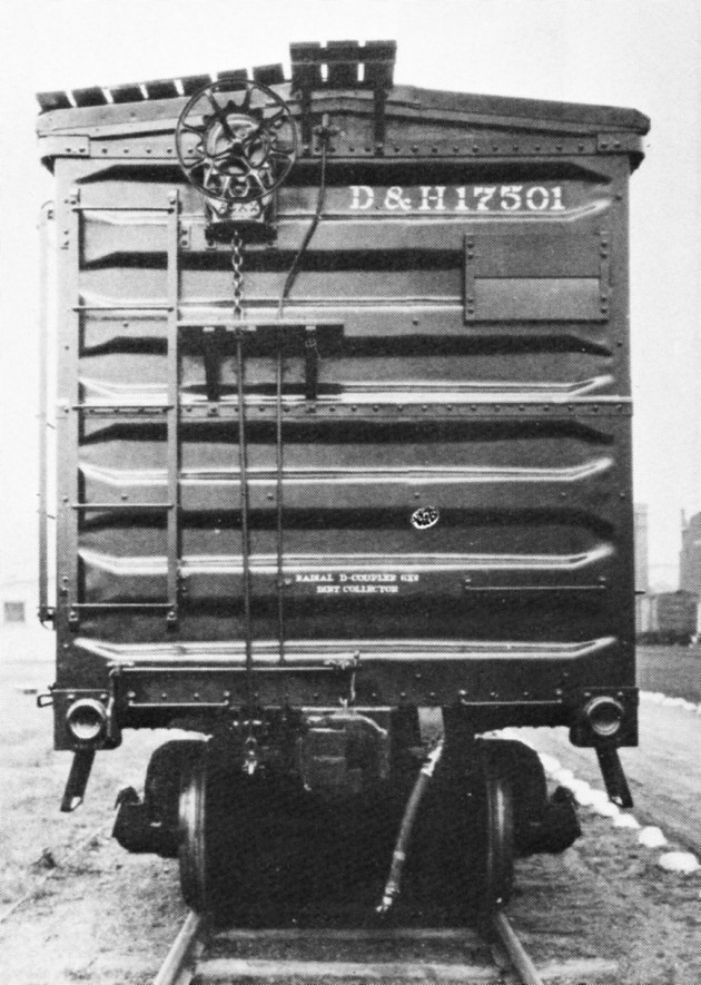
Green Island 17501 showing detail of reverse Hutchins end,  builders (image courtesy R.P.I. D&H Collection)


(image courtesy Robert A. Lijestrand)

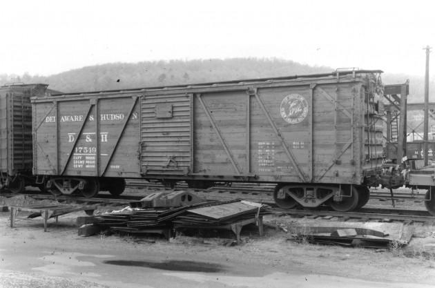
The ubiquitous “Green Island” single sheathed boxcar. Oneonta Shops built the bulk of  the D&H’s rolling stock, but the Green Island shops built this batch. There were 100 cars in the group, #17501-17600, built 1931. These cars were built on a construction philosophy similar to that of the Fowler Patent and Candian Pacific 40′ “Dominion” cars. These featured “Z” channel bracing, reversed Hutchins ends, National B-1 trucks, Murphy Improved roof, and an 8′-7″ inside height.

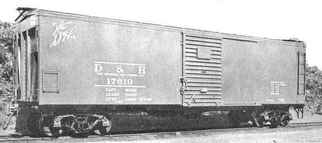
Oneonta Shops “near” AAR ’32 Standard, 40′, all steel “semi-clone”, built 1930, series 17601-17625. This car series, although not a true clone,  and equipped with a recessed “Z”-braced, steel end, was built following  the ’32 AAR plan, that was published in late 1929. Often the AAR would publish their newest spec.  in advance of acceptance, for the “Enlightnment of the RR Industry”. The actual spec. might not be ratified and made a legitmate standard by the committee-at-large for a year or more after initial publishing. Inside height was 9″-1″.


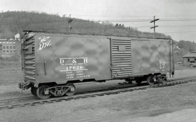
This could be considered a Company “Builder’s Photo” of the first of her kind. Again, this is a product of the D&H’s Green Island Shops, and shown at Oneonta. The car is #17626, and is an all-welded AAR ’32 Standard true “Clone”. The year is 1934, and 100 cars of this type, in this series were built, #17626-17725, between 1934 and 1937.

The car utilized internal ribs, with external steel sheathing welded to them from the inside. TIG (Tungsten Inert Gas) and MIG (Metal Inert Gas) welding did not exist at this time, so the bonds were made with the old fashioned Arc welding process. Unlike modern methods,  Arc welding generates a tremendous amount of heat, and distributes it  over a wide area.  If you look closely, you’ll note the semi-uniform waves or “ripples” in the side sheathing; a permanent deformitity created by the extreme heat of the Arc. Inside height was 9′-4 1/2″.

The famous D&H 100 Years “Anthracite Circle” was not applied to the car when new, not becoming part of the D&H freight car paint scheme until the arrival of the Bethlehem Steel-built “Fishbelly” twin hoppers, starting in 1939. This car and her sisters received that herald begining  in 1940.

(image courtesy Norm Buckhart/Protocraft.com)

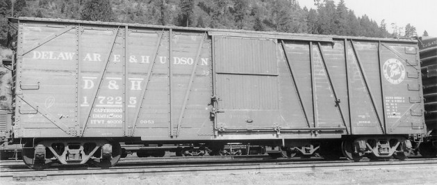
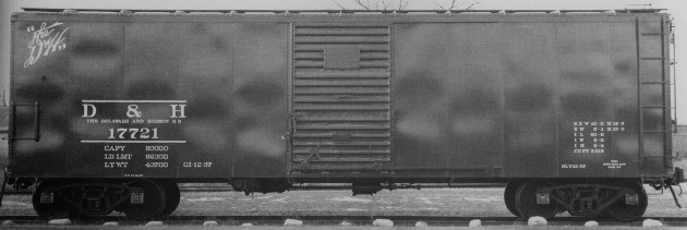
Here’s another builder’s image of ’32 clone sister car #17721. The image above this one shows the very first car in the series, and this one shows almost the last; the final car in this group being #17725. When these cars were first starting to be built in 1934, the Murphy raised-panel roof was new on the freight car scene. The D&H, always on the cutting edge of new technology, quickly adoted this new roof for these builds.  Looking at the eaves of this broadside, one can just make out the edges of the raised panels, visible between each roof rib.

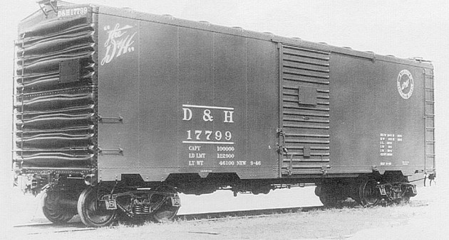
American Car & Foundry (ACF), AAR ’44 Standard, #17799, built 1946. Series #17726-17799.  The last 25 of these cars #17775-17799 were equipped with auto parts racks by Oneonta Shops, so that they could carry new radiators from Ford Motor Company’s plant in Anderson, Indiana, to their assembly plant in Sommerville, MA.  They remained in this dedicated service until the spring of 1956, at which time the racks were removed, and these cars were placed in regular interchange service with their sisters. All-welded construction, 4/4 improved Dreadnaught ends, Murphy Raised-panel roof. Car was painted all red with black ends only, when delivered new. 10′-4″ inside height.

The dedicated radiator service continued through 1956 and beyond, but in a different car. In that same year the D&H bought eleven (11), 50′ PRR double door X33’s. Oneonta Shops equipped these cars with racks, and these cars were then placed in that service.

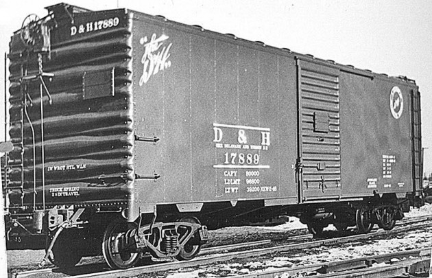
Oneonta Shops #17889, built 1947-48, series 17800-17899. These cars were  home-built to the AAR ’44 Std. spec. All-welded construction, with a unique 14 panel side, 3/4 Improved Dreadnaught ends, Murphy raised-panel roof, and 10′ inside height. This series of cars was one of the late-built types, that still retained the older 10′-0″ IH of the original ’37 Standard. Entire car painted red.

(not shown) Oneonta Shops-built, AAR ’44 Std. spec boxcars, series 17900-18049…

(image courtesy Jonathan Ferraro)

(image courtesy Robert A. Lijestrand)

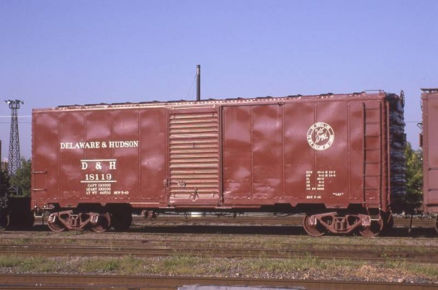
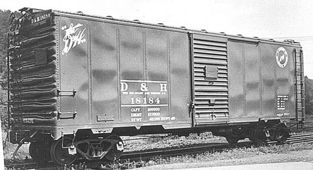
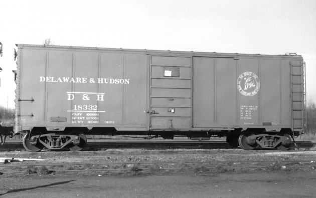
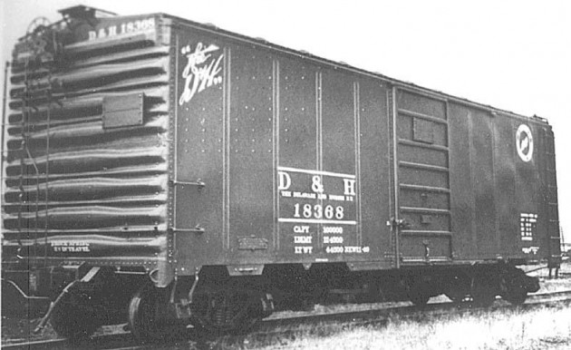
Oneonta Shops #18119, #18184, #18332 and #18368, built 1949, series 18100-18399. These cars were home-built to the AAR ’44 Std. spec. All-welded construction with double-welded, “flat side ribs”, 3/4 Improved Dreadnaught ends with added square top rib, Murphy diagonal-panel roof,  10′-6″ inside height. Of the 300 cars in this series, the first 200 were equipped with Youngstown doors, and last 100 with seven-panel Superior doors. Note the unsual, purpose-applied rivet patterns on the first three panels of #18368. Cars were painted all red.


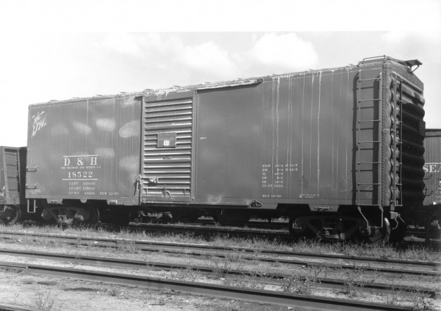
Pullman Standard “PS-1″ # 18522, built 1950, series #18400-18899.  10′-6” inside height. Although built in 1950, and with only two year old Pullman-delivered paint in this 1952 view, note the conspicuous omission of the Company’s Anthracite Circle medallion. The Anthracite “100 Years”  logo was adopted as a standard part of Company freight car lettering in 1939, but it is obvious that even though it was a standard part of the D&H Company paint, not all rolling stock got the complete treatment. This car is actually painted in the pre-1939 scheme, that did not sport the Anthracite Circle. Body of the car is red, with black car cement ends; the “traditional” Pullman Standard paint job of the era.

The  first Bridge Line Circle medallion was adopted in 1951, with the delivery of the Bethlehem-built AAR Std. offset twin hoppers (the medallion was 41″ in diameter). The second order of Pullman Standard PS-1 boxcars also received it, but in a smaller 33″ version. (image courtesy Robert A. Lijestrand)

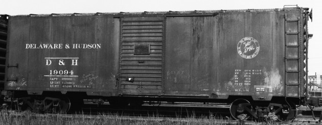
Here we see a member of the second order of Pullman Standard PS-1’s,  series #18900-19399. Built March of 1951, this is the first of the D&H boxes to wear the newly devised paint scheme.  DELAWARE & HUDSON is spelled out on the carside in large letters, along with the addition of the 33″ “Bridge Line” medallion. Gone is the script “the D&H”, the Anthracite Circle, and the words “THE DELAWARE AND HUDSON RR” spelled out in 2″ letters, just below the reporting marks. Car is painted red with black car cement roof and ends. (image courtesy Norm Buckhart/Protocraft.com)

Builder’s photo of Pullman Standard PS-1, series #19400-19899, built 1952. Car is painted all red with black ends and sports the 41″ “Bridge Line” medallion, new on boxcars for 1952, is the same size as the one used on the AAR Standard offset twin hoppers. This was the last series of cars delivered to the D&H with trains still being pulled by steam locomotives. All cars ordered (and delivered) from this point forward would be a part of the diesel-era.