In the 1920’s trains were getting longer and heavier, and larger steam switchers were needed to handle the load. To meet this need, and rather than buying new power, the frugal Delaware and Hudson chose to build a group of fourteen, heavy 0-8-0 steam switchers. They were home-built at their Colonie Shops from 1926 to 1930. The Company used running gear, frames and boilers from older, then in-service 1000 Series, E-5 Class 2-8-0’s to create these large, powerful 0-8-0’s.

Firemans’ side view of home-built heavy 0-8-0 class B-7, #157 as she sits on the ash pits at the Carbondale engine facility in 1940. This loco is typical of the class with all locos being nearly identical, displaying only minor differences in tender length and capacity. #157 was one of the short-tendered variants. (Ed Hermans collection, image courtesy Robert A. Liljestrand)

Engineer’s side view of B-7 Class #157 resting between switching assignments in the Carbondale Yard, August 10, 1952. (Joseph A. Smith collection)

A second shot of the engineer’s side of the loco, as she sits on the ash pit at Colonie in 1944. (Robert A Dunn Photo)
]_________________________________[
I’ve scratchbuilt many “O” steam locos over the years, but I am always on the lookout for a suitable “donor loco” for a given project. Scratchbuilding, although VERY satisfying, is the longest path one can take in creating a desired prototype. As an example, the Erie S-Class Berk is very unique, and although US Hobbies did import the NKP and C&O Berks in quantity, NEITHER unit makes an acceptable donor as the base model for an Erie Berk conversion, so scratchbuilding is the ONLY answer.
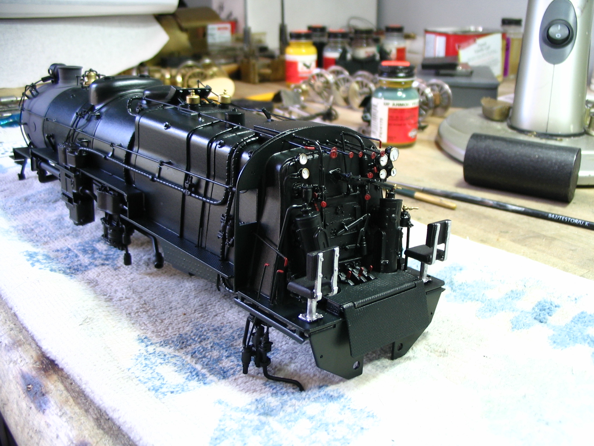
In starting the D&H #157 project, I also thought about other 0-8-0’s that had been imported, but most are too small, and sport 51″ drivers. The D&H B-7’s were built from older consolidations and were equipped with 57″ drivers. After a bit of hunting, I determined that my best course of action was to walk the same path as the D&H did, and use a small consolidation as a donor. I looked at the plentiful PRR H-8, 9, 10 Class consols, but the drivers are too large at 62″. After a bit more investigating, I located a US Hobbies UP 2-8-0 with 57″ drivers…a GREAT place to start. I bought the loco, and this is how it look upon arrival.

Not a horrible paint job, but those “steam-roller” 0.172 “old school” driver tires have got to go!!! In fact, so does the paint and lettering. Next stop is the lacquer thinner bucket and the bead blaster. And that tender…what to do with that? After a little thought, it occured to me that all I needed to do was shorten it, convert the bunker to coal, and I could use it on my Erie C-3a 0-8-0, which were equipped with coal Vandys by the builder, given that road’s early Harriman relationship.

All stripped and whistle clean, ready to be “de-constructed”…

Here’s the model with its drivers rough-turned to 0.145. I still need to press the centers in an extra 0.020, and remove material from the rear of the driver center. Then fine-turn the face to 0.130 and drop the flanges to 0.030. This final machining will give me a 0.005 to 0.007 raised face on the driver tire, which is a HUGE help in keeping a nice, crisp edge when painting the driver tires white, a D&H Company Standard on all in-service locos, from small switchers to Challengers. Tires were initially painted white when locos were new as well as after shoppings, but were also repainted on a regular basis as needed, keeping them bright white for the life of the loco. Note how the counterweights now hang out prototypically past the tire edge and driver face after the initial turning.
]_________________________________[
If one takes note, many early steam locos on The Anthracite Roads were equipped with a “kicked back” rear driver, be it a 2-6-0, 4-6-0, 2-8-0, or 4-8-0. In other words, rather than all driver axle centers being evenly spaced, the last axle in the driver set was moved rearward. This was done to extend the loco’s wheelbase because they lacked a trailing truck, providing additional support for the huge, anthracite-burning Wooten firebox.
Originally starting out as a 2-8-0, and then being converted to an 0-8-0, the Wooten-equipped D&H B-7 also has a kicked back rear axle. In addition, the loco frame’s original tailbeam will need to be modified to reflect the new prototype. Below is a basic 1/8″ scale drawing of the B-7.

(Draw by the late Lawrence C. Himrod, Binghamton, NY, March 15, 1963, Matt Forsyth collection)

This is a closeup image of the required tailbeam, and also shows the rearward-extended rear driver axle in better detail.

After complete dissassembly of the loco, the fame was put in a vice and the old tailbeam was cut off with a hacksaw. It was then milled on the Sherline miller using a 1/4″ 4-flute mill to create a step to accept the new tailbeam extension. While I had the frame fixtured, I also cut back the trailing edge of the rear bearing slot to achieve the kick-back offset and the correct B-7 rear driver spacing. After the new beam is fabricated and installed, I will sweat a section of brass bar against the leading edge of the bearing slot to restore the original slot dimensions, and complete the kick-back.

This is a full broadside of the frame post step and bearing slot cutting…

After cutting two short lengths of 2 ¼” x 3/4″ x 3/16″ thick brass bar, I soldered the two together to make a sandwich. I blued one side and after creating a paper template of the new beam from 100 lb. cardstock, I overlayed the template on the brass and scribed in the design. I fixtured the brass in the Sherline and milled out the openings and all the outside surfaces. I left some excess material on the inside of the top beam of the forward hole (red arrow). This is a mating surface and I temporarily need that extra material left in place for added rigidity. After the new beam is soldered on to the frame, I will go back in and mill that material away to a final, finished shape.

3/4 view, front and top…

3/4 view rear and top…

The new extension is test-fit to the frame. Note the line scribed into the bluing past the trailing edged of the bearing slot (red arrow). The material to the right of the line still needs to be removed to complete the kick-back. I have left it in place temporarily to add strength to the tail beam solder joint area. Once the beam is completely soldered in place, I will mill the rear bearing slot back to this line, completing the axle re-spacing.

Once satisfied with the final fit and dimensions, the two halves are heated, separated, and the excess solder cleaned off…

The two halves placed in their correct positions, ready for final fitment…

Final fitting, and everything looks great…

New beam has been fixtured to the frame and soldered into place. Soldering was accomplished with a standard Bernz-o-matic propane plumber’s torch with a pencil tip, rosin core solder, and Nokorrode paste flux.

Post-soldering view #2

Post-soldering view #3

Post-soldering view #4

Final post-soldering machining on the tailbeam to remove excess material is complete, as well as the addition of the new bearing slot filler. The drivers and springs have been dropped back in, kick-back is complete, and all looks good.

Here’s one last view, showing the new tail beam in detail. I still need to final-machine the drivers, as well as extend the last segment of the side rods to match the new kick-back. In all reality, I could have just “fudged it” and not worried about adding an accurate, prototypical D&H tail beam, but with no trailing truck, that beam will be a very obvious on the model, and anything other than a correct one would stick out like a sore thumb.


